Jaw Style Coupling Choice Process
The choice process for determining the right jaw coupling size and elastomer needs making use of the charts proven about the following pages. There are 3 parts to get picked, two hubs and one particular elastomer. When the shaft dimension of your driver and driven with the application are of your exact same diameter, the hubs selected are going to be the exact same. When shaft diameters vary, hubs picked will differ accordingly.
Info vital just before a coupling is often picked:
HP (or KW) and RPM or Torque of driver
Shaft sizes of driver and driven tools and corresponding keyways
Application description
Environmental ailments (i.e. intense temperature, corrosive situations, area limitations)
Steps In Choosing A Jaw Coupling
Stage one: Ascertain the Nominal Torque of the application by utilizing the following formula:
Nominal Torque = in-lb = (HP x 63025)/RPM
Nm = (KW x 9550)/RPM
Stage 2: Applying the Application Services Variables Chart 1 pick the support component which most effective corresponds for your application.
Phase 3: Calculate the Style and design Torque of the application by multiplying the Nominal Torque calculated in Step one by the Application Support Aspect established in Step two.
Layout Torque = Nominal Torque x Application Services Factor
Phase 4: Working with the Spider Performance Data Chart 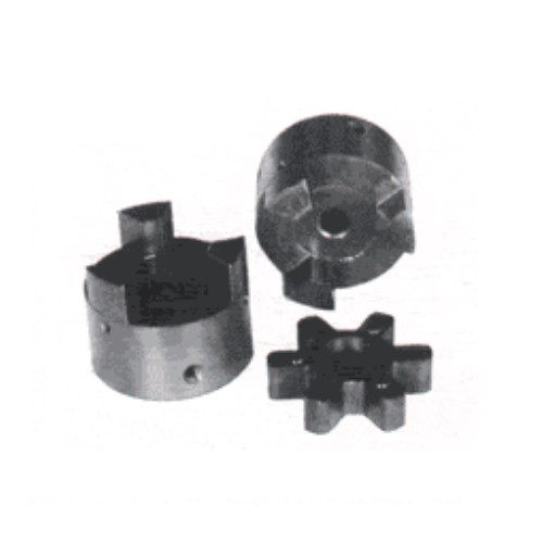 2, select the elastomer material which ideal corresponds for your application.
Step 5: Utilizing the Jaw Nominal Rated Torque Chart three , find the appropriate elastomer material column for that elastomer picked in Step 4.
Scan down this column towards the to start with entry wherever the Torque Worth from the ideal column is higher than or equal on the Style and design Torque calculated in Step three.
After this worth is found, refer to your corresponding coupling dimension in the initially column from the Jaw Nominal Rated Torque Chart 3 .
Refer to your highest RPM value for this elastomer torque capability to guarantee the application requirements are met. When the necessity is not really pleased at this time, another kind of coupling could possibly be required for your application. Please consult Lovejoy engineering for help.
Phase 6: Review the application driver/driven shaft sizes to your highest bore size available within the coupling selected. If coupling bore size just isn’t huge adequate for that shaft diameter, decide on the following biggest coupling that may accommodate the driver/driven shaft diameters.
Step seven: Utilizing the UPC amount selection table , discover the acceptable Bore and Keyway sizes expected and find the number.
Jaw Coupling Selection Procedure
Tags: